Search filter
Filter
Reset- Product data sheet (744)
- Installation drawing (730)
- Installation instructions (236)
- Tender texts (157)
- Product scale drawing (126)
- Certificate (90)
- Declarations of performance (83)
- 3D model (77)
- Declaration of conformity (57)
- Cable plan (38)
- Environmental declaration (30)
- Wiring diagram (28)
- User manual (23)
- Flyer/folder (13)
- Product brochure (13)
- Supplementary sheet (12)
- Type examination certificate (6)
- Inspection certificate (6)
- T&C / Data Protection (6)
- Software (5)
- Supplier information (4)
- Product shot (3)
- Safety analysis (1)
- Evaluation/comment (1)
- Customer information (1)
2490 results found

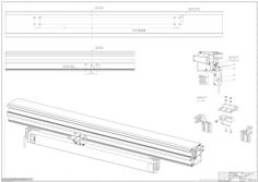
Installation drawing OL 90 N with E 212 horizontal
(PDF | 439 KB)
Powerchain roof window Hueck 85 E
(PDF | 171 KB)
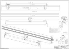
E 170 scissor drive
1 E 170 128689-03 … max. … 1 max. ≤12 … a 900-1600 ≥ 300 E 170/2 - 2400 1600-2400 ≥ 300 35 20 22 260 mm E 170/2 - 1600 436,5 mm E 170/2 - 2400 786,5 mm Ø12 11,5 E 170/2 - 1600 11,5 ≥ 300 96 35 A 85 a b [mm] 550-1200 E 170 a/2 a/2 a a/2 … Ø12 273,5 63,5 a/2 353 a … 2 20 B a 526,5 20 (32,5) Ø12 526,5 20 a 85 (4) (4)14/20 20 286,5 478,5 … 20 … 1 a/2 a … a … 4 … 286,5 … 20 … 4 … 2 478,5 a/2 20 … 20 L … 478,5 … L … 85 85 … mm 12 mm 2x 786,5 526,5 1a … 3 mm … 4 1b 526,5 (4) 786,5 B B 526,5 (4) 526,5 … 20 … 286,5 … 2x B 20 478,5 20 … a/2 286,5 a 20 … 14/20 20 11,5 478,5 … mm … 14/20 20 20 a 1573 11,5 … Ø12 … 1573 Ø12 20 a/2 1600 1053 A … a/2 1600 Ø12 ( 4) 286,5 526,5 a 286,5 1053 (32,5) … a/2 Ø12 526,5 63,5 E 170/2 - 2400 (32,5) … 1573 a 273,5 a 526,5 L a/2 273,5 … 526,5 (4) 20 14/20 a/2 20 … (32,5) 11,5 11,5 63,5 20 20 1573 … Ø12 … 5 (32,5) 20 … 478,5 L - … mm Ø12 14/20 … 5 11,5 176,5 20 526,5 286,5 20 786,5 (4) 20 11,5 (4) 20 (4) 14/20 14/20 436,5 14/20 (4) 35 B … 526,5 786,5 786,5 873 176,5 176,5 4x M5×16 … 436,5 (32,5) Ø12 20 a/2 1053 … 176,5 … 63,5 1600 273,5 (32,5) … 1600 873 A … 20 1053 900 (32,5) 176,5 (4) 176,5 20 11,5 (4) 14/20 … 4x 5×20 1573 786,5 (4) 273,5 a/2 20 a 1573 11,5 a 20 526,5 14/20 35 a/2 a 900 (32,5) … 14/20 … 1600 526,5 14/20 20 … 20 11,5 … (32,5) 85 353 Ø12 … 1053 1573 1600 4x M5×16 14/20 85 273,5 176,5 … 273,5 436,5 Ø12 63,5 85 35 20 176,5 20 … 3 1053 4x 5×20 873 436,5 260 35 11,5 … (32,5) Ø12 85 14/20 11,5 a 230 V Ø12 … 786,5 14/20 a/2 Ø12 E 170/2 - 1600 (32,5) … 273,5 176,5 14/20 260 20 11,5 20 (4) 14/20 20 … 35 1600 … 873 520 … 1053 436,5 … 176,5 273,5 900 20 20 (32,5) M5×16 353 873 (4) (4) 20 20 11,5 (32,5) 11,5 35 520 10x M5×16 273,5 ID 151531 260 Ø12 10x 5×20 ( 4) 900 A 9x M5×16 353 520 (32,5) 9x 5×20 356x 85 3547 11,5 273,5 547 E 170/2 - 1600 E 170/2 - 2400 85 85 E 170 6x 5×20 85 900 E 170 a 85 35 85 353 20 273,5 35 35 547 35 162 85 35 a [mm] E 170 b Ø12 85 b b max.60° b 20 100 kg ≤12 s … s 478,5 a/2 a … [mm] 360° [mm] 160 4x 2,5 150 7x … 140 10,5x 7,5 130 13,5x 10 … GEZE GmbH Reinhold-Vöster-Strasse 21–29 71229 Leonberg Germany Tel.: 0049 7152 203-0 Fax: 0049 7152 203-310 www.geze.com s … 5 Nm
(PDF | 8 MB)
Powerchain Raico Wing 105 DI
(DOCUMENT | 5 MB)
Block diagram OL 320
(DWG | 1 MB)
Powerchain roof window Heroal C50
(PDF | 237 KB)
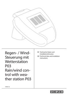
Technical data and installation instructions rain / wind control unit with weather station P 03
Regen- / WindSteuerung mit Wetterstation P03 Rain/wind control with weather station P03 139860-02 DE Technische Daten und Installationshinweise GB Technical data and installation instructions Wetterstation P03 / Weather station P03 Inhaltsverzeichnis Symbole und Darstellungsmittel / Symbols and means of representation … Produkthaftung / Product liability … 2 … Lieferumfang / Scope of delivery … 2 Produktbeschreibung / Product description … Aufbau der Platine / Circuit board design … 3 Montage / Mounting … Standort / Location … Montage des Halters / Mounting the retainer … Montage der Wetterstation / Mounting the weather station … Montage des Steuergeräts / Mounting the control device … 4 Inbetriebnahme / Commissioning … 5 Betrieb / Operation … 6 Wartung / Maintenance … 11 … Technische Daten Wetterstation / Weather station technical data … 12 … Abmessungen / Dimensions … 13 Wetterstation P03 / Weather station P03 Symbole und Darstellungsmittel / Symbols and means of representation Warnhinweise / Warnings In dieser Anleitung werden Warnhinweise verwendet, um Sie vor Sach- und Personenschäden zu warnen. XX Lesen und beachten Sie diese Warnhinweise immer. XX Befolgen Sie alle Maßnahmen, die mit dem Warnsymbol und Warnwort gekennzeichnet sind. In these instructions, warnings are used to warn against material damage and injuries. XX Always read and observe these warnings. XX Observe all the measures that are marked with the warning symbol and warning word. Warnsymbol / Warnwort / Bedeutung / Meaning Warning Warning word symbol Gefahren für Personen. WARNUNG Nichtbeachtung kann zu Tod oder schweren Verletzungen führen. warning – VORSICHT CAUTION Danger for persons. Non-compliance can result in death or serious injuries. Informationen zur Vermeidung von Sachschäden, zum Verständnis oder zum Optimieren der Arbeitsabläufe. Information on avoiding material damage, understanding a concept or optimising the processes. Weitere Symbole und Darstellungsmittel / Further symbols and means of representation Um die korrekte Bedienung zu verdeutlichen, sind wichtige Informationen und technische Hinweise besonders herausgestellt. Important information and technical notes are emphasised in order to illustrate the correct operation. Symbol Bedeutung / Meaning bedeutet „Wichtiger Hinweis“ means “important note” bedeutet „Zusätzliche Information“ means “additional information” XX Symbol für eine Handlung: Hier müssen Sie etwas tun. XX Halten Sie bei mehreren Handlungsschritten die Reihenfolge ein. Symbol for an action: Here you have to do something. XX Observe the sequence if there are several action steps. Produkthaftung / Product liability Gemäß der im Produkthaftungsgesetz definierten Haftung des Herstellers für seine Produkte sind die in dieser Broschüre enthaltenen Informationen (Produktinformationen und bestimmungsgemäße Verwendung, Fehlgebrauch, Produktleistung, Produktwartung, Informations- und Instruktionspflichten) zu beachten. Die Nichtbeachtung entbindet den Hersteller von seiner Haftungspflicht. Für Änderungen der Normen und Standards nach Erscheinen der Installationsanleitung ist GEZE nicht haftbar. In accordance with the liability of manufacturers for their products as defined in the German “Produkthaftungsgesetz” (Product Liability Act), the information contained in these instructions (product information and proper use, misuse, product performance, product maintenance, obligations to provide information and instructions) is to be observed. Non-compliance releases the manufacturer from its statutory liability. GEZE is not liable for changes to the norms and standards after the installation instructions have been published. … Lieferumfang / Scope of delivery … Wetterstation P03 / Weather station P03 Lieferumfang / Scope of delivery Die Regen-/Wind-Steuerung (Mat.Nr. 91529) besteht aus folgenden Komponenten: àà Steuergeräte Regen/Wind àà Wetterstation P03 (Mat. Nr. 139579) Optional erhältlich: àà Anzeigemodul mit zwei LEDs (Mat.Nr. 29238) The rain/wind control unit (Mat. No. 91529) consists of the following components: àà Rain/wind control devices àà Weather station P03 (Mat. No. 139579) Optionally available: àà Display module with two LEDs (Mat. No. 29238) … Produktbeschreibung / Product description Die Wetterstation P03 misst Temperatur und Windgeschwindigkeit und erkennt Niederschläge. Die P03 gehört zum Lieferumfang der Regen-/Wind-Steuerung. The weather station P03 measures the temperature and wind speed and recognises precipitation. The P03 belongs to the scope of delivery of the rain/wind control unit. … Aufbau der Platine / Circuit board design … 1 … 3 Montage / Mounting … Standort / Location … Steckplatz für Anschluss der Steuerung / Slot for connecting the control unit 1: +24 V DC 2: GND 3: Daten / Data Steckplatz für Kabelverbindung zum Niederschlags sensor im Gehäusedeckel / Slot for cable connection to the precipitation sensor in the housing cover Wählen Sie eine Montageposition am Gebäude, wo Wind, Regen und Sonne ungehindert von den Sensoren erfasst werden können. Es dürfen keine Konstruktionsteile über der Wetterstation angebracht sein, von denen noch Wasser auf den Niederschlagssensor tropfen kann, nachdem es bereits aufgehört hat zu regnen oder zu schneien. Die Wetterstation darf nicht durch den Baukörper oder zum Beispiel Bäume abgeschattet werden. Unter der Wetterstation muss mindestens 60 cm Freiraum belassen werden, um eine korrekte Windmessung zu ermöglichen und bei Schneefall ein Einschneien zu verhindern. Select a mounting position on the building where wind, rain and sun can be detected unhindered by the sensors. There may not be any constructional parts over the weather station from which water can still drop onto the precipitation censor after it has already stopped raining or snowing. Shadows, for example from the building or trees, may not fall onto the weather station. There has to be at least 60 cm clearance under the weather station in order to enable correct wind measurement and, in case of snow fall, to prevent it being snowed over. … Wetterstation P03 / Weather station P03 Montage / Mounting àà Die Wetterstation muss an einer senkrechten Wand (bzw. einem Mast) (1) angebracht werden. àà The weather station has to be mounted on a vertical wall (or a mast) (1). … àà Die Wetterstation muss in der Querrichtung horizontal (waagrecht) (2) montiert sein. … àà In the cross direction the weather station has to be mounted horizontally (2). … Montage des Halters / Mounting the retainer Die Wetterstation beinhaltet einen kombinierten Wand-/Masthalter. Der Halter ist bei Lieferung mit Klebestreifen an der Gehäuserückseite befestigt. The weather station contains a combined wall/mast retainer. On delivery the retainer is fastened to the housing rear by means of adhesive strips. XX XX XX XX Halter senkrecht an Wand oder Mast befestigen. Bei Wandmontage: ebene Seite zur Wand, halbmondförmiger Steg (1) nach oben. … Fasten the retainer vertically to the wall or mast. For wall-mounting: flat side to the wall, crescentshaped bar (1) upwards. XX Bei Mastmontage: geschwungene Seite zum Mast, Steg (1) nach unten. XX For mast mounting: curved side to the mast, bar (1) downwards. … 5 Montage / Mounting Wetterstation P03 / Weather station P03 … Montage der Wetterstation / Mounting the weather station … .1 Allgemeine Hinweise / General information Öffnen Sie die Wetterstation P03 nicht, wenn Wasser (Regen) eindringen kann: Schon wenige Tropfen könnten die Elektronik beschädigen. Do not open the weather station P03 if water (rain) can ingress: Even just a few drops can damage the electronics. Bei der Montage ist darauf zu achten, dass der Temperatursensor (kleine Platine an der Unterseite des Gehäuses) nicht beschädigt wird. Auch die Kabelverbindung zwischen Platine und Regensensor darf beim Anschluss nicht abgerissen oder geknickt werden. Ensure during mounting that the temperature sensor (small circuit board at the lower part of the housing) is not damaged. Also ensure that the cable connection between the circuit board and the rain sensor is not ripped off or bent. … .2 Vorbereitung der Wetterstation / Preparing the weather station … 2 … 4 … 2 … 4 Deckel mit Regensensor / Cover with rain sensor Rasten des Deckels / Latches of the cover Platine / Circuit board Gehäuse-Unterteil / Housing lower part Der Deckel der Wetterstation mit dem Regensensor ist am unteren Rand rechts und links eingerastet. XX Deckel von der Wetterstation abnehmen. Vorsicht! Sachschaden! XX Sorgfältig vorgehen, um die Kabelverbindung zwischen der Platine im Unterteil und dem Regensensor im Deckel nicht abzureißen (Kabel mit Stecker). XX XX Kabel für die Spannungsversorgung und Busanschluss durch die Gummidichtung an der Unterseite der Wetterstation führen. Spannung und Bus an die dafür vorgesehenen Klemmen anschließen. Die Zuleitung zur Wetterstation darf maximal 30 m lang sein. Der Anschluss erfolgt mit handelsüblichem Telefonkabel (J-Y(ST)Y … × … × 0,8). The cover of the weather station with the rain sensor is latched in on the right and left of the lower edge. XX Remove the cover from the weather station. Caution! Material damage! XX Proceed carefully so that you do not rip off the cable connection between the circuit board in the lower part and the rain sensor in the cover (cable with plug). XX … Lay the cables for the voltage supply and the bus connection through the rubber seal at the lower part of the weather station. Wetterstation P03 / Weather station P03 XX Montage / Mounting Connect the voltage and bus to the corresponding terminals. The cable to the weather station may have a maximum length of 30 m. Connection is carried out with a common phone cable (J-Y(ST)Y … × … × … ). … .3 Anbringen der Wetterstation / Attaching the weather station Die Wetterstation muss so montiert werden, dass die Sensorfläche des Regenfühlers im Winkel von 45° nach unten weist. Regen und Wind müssen ungehindert auf das Gerät einwirken können. The weather station has to be mounted so that the sensor surface of the rain sensor forms an angle of 45° downwards. It must be possible for the rain and wind to act unimpaired on the unit. XX Deckel über das Unterteil stülpen. Der Deckel muss rechts und links mit einem eindeutigen „Klick“ einrasten. XX Prüfen, ob Deckel und Unterteil richtig eingerastet sind. Die Abbildung zeigt die geschlossene Wetterstation von unten mit der Raste (1). XX Put the cover onto the lower part. The cover has to latch in on the right and left with an audible “Click”. XX Check whether the cover and lower part are latched in correctly. The figure shows the closed weather station from below with the latch (1). … Gehäuse von oben in den montierten Halter schieben. Die Zapfen des Halters müssen dabei in den Schienen des Gehäuses einrasten. XX Slide the housing from above into the mounted retainer. The pins of the retainer have to latch into the rails of the housing. XX … Montage / Mounting … Wetterstation P03 / Weather station P03 Montage des Steuergeräts / Mounting the control device Die Leitungsverlegung und der Anschluss dürfen nur durch eine zugelassene Elektrofirma durchgeführt werden. àà Das Steuergerät darf nicht im Außenbereich montiert werden. àà Zweckmäßigerweise wird es in der Nähe der Wetterstation montiert. àà Die Leitungslänge darf max. 30 m betragen. Laying and connection of cables may only be carried out by an approved electrician. àà The control device may not be mounted outdoors. àà It makes sense to mount it near the weather station. àà The max. cable length amounts to 30 m. Kabelverlegung / Cable length … 2 x … x … mm … (max. 30 m) … 3x1.5 mm 230 V AC … 2 … x … x … mm … 2 … Wetterstation / Weather station Steuergerät / Control device … 3 … potentialfreie Schaltausgänge / Potential-free switching outputs Anzeigeeinheit / Display unit * bei 230 V – … x 1,5 mm2 / at 230 V – … x … mm2 * bei 24 V – … x … x 0,8 mm2 / at 24 V – … x … x … mm2 … Wetterstation P03 / Weather station P03 … Inbetriebnahme / Commissioning Inbetriebnahme / Commissioning WARNUNG! Lebensgefahr durch Stromschlag! XX Beim Anschluss der Wetterstation alle zu montierenden Leitungen spannungslos schalten (Netzsicherung des Steuergerätes ausschalten). XX Sicherheitsvorkehrungen gegen unbeabsichtigtes Einschalten treffen. Vorsicht! Zerstörung der Wetterstation oder mit ihr verbundene elektronische Geräte! XX Auf korrekten Anschluss achten. Nach dem Auspacken ist das Gerät unverzüglich auf eventuelle mechanische Beschädigungen zu untersuchen. Wenn ein Transportschaden vorliegt, ist unverzüglich der Lieferant davon in Kenntnis zu setzen. Die Wetterstation darf bei Beschädigung nicht in Betrieb genommen werden. XX Wenn anzunehmen ist, dass ein gefahrloser Betrieb nicht mehr gewährleistet ist, so ist die Anlage außer Betrieb zu nehmen und gegen unbeabsichtigten Betrieb zu sichern. Die Wetterstation darf nur als ortsfeste Installation betrieben werden, das heißt, nur in eingebautem Zustand und nach Abschluss aller Installations- und Inbetriebnahmearbeiten und nur im dafür vorgesehenen Umfeld. WARNING! Danger of fatal injury via electric shock! XX When connecting the weather station deenergize all the cables to be mounted (switch off the mains fuse of the control device). XX Take precautionary measures against unintentional activation. Caution! Destruction of the weather station or the electronic devices connected to it! XX Ensure proper connection. Inspect the device immediately after unpacking for any mechanical damage. If there is any transport damage, inform the supplier immediately. The weather station may not be put into operation if damaged. XX If it is to be assumed that safe operation is no longer possible, take the system out of operation and secure it against unintentional operation. The weather station may only be operated as a fixed installation, meaning only in the built-in state and after all the installation and commissioning work has been completed and only in the specified environment. … Betrieb / Operation Vorsicht! Sachschaden! Bei einsetzenden Regen, kann je nach Regenmenge und Außentemperatur eine gewisse Zeit vergehen, bis die Steuerung „Regenalarm“ erkennt. Es dürfen sich keinesfalls empfindliche Geräte, die durch ein „spät“ schließendes Fenster beschädigt werden könnten, in diesem Bereich befinden. Caution! Material damage! When it starts raining, it may take some time until the control unit recognises "Rain alarm", depending on the amount of time and the outdoor temperature. Under no circumstances may sensitive devices that could be damaged by a window closing too "late" be located in this area. … Betrieb / Operation Wetterstation P03 / Weather station P03 … 3 (a) (b) … 7 LED 17 … 1m/s 2m/s 4m/s 8m/s F1 … LED ON OFF … 8 13 14 15 … 16 … L1 N PE 3x1.5 mm … 14 … LEDs … W R + 230 V AC 50/60 Hz 12 … 5 … x … x … mm … W R 2x1.5 mm2 2x1.5 mm2 … x … x … mm … (max. 30 m) 10 … 11 … 3 … 2 (a) (b) … 4 … 6 … 8 10 Primärsicherung M 100 mA / Primary fuse M 100 mA Einstellung der Betriebsart mit Jumper / Setting of operating mode with jumper Relais getrennt / Separate relay operation Relais gemeinsam / Common relay operation Einstellung der Windgeschwindigkeit / Setting of the wind speed Kontroll-LED (blinkt, wenn Verbindung zur Wetter station OK ist) / Control LED (flashes if connection to weather station is OK) LED (Wind) / LED (wind) LED (Regen) / LED (rain) Windalarm / Wind alarm Signal … 10 11 12 13 14 15 16 17 Wetterstation / Weather station Anzeigemodul / Display module Wetterstation mit Regenfühler, Windfühler und Außen temperaturfühler / Weather station with rain sensor, wind sensor and outside temperature sensor potentailfreie Schließer max. … A / 230 V / Potential-free NO contacts max. … A / 230 V Steuergerät für Regen-/Windsteuerung / Control device for rain/wind control unit Netz / Power Relais Kontakt Wind / Relay contact wind Relais Kontakt Regen / Relay contact rain Trafo / Transformer Wetterstation P03 / Weather station P03 … .1 Wartung / Maintenance Einstellung der Windgeschwindigkeit / Setting of the wind speed Durch Addition der Werte können alle Kombinationen zwischen … m/s und 15 m/s eingestellt werden. (z.B. … m/s + … m/s = … m/s) All the combinations between … m/s and 15 m/s can be set by adding the values. (e.g. … m/s + … m/s = … m/s) … .2 Einstellung der Betriebsart mit Jumper / Setting of operating mode with jumper Relais getrennt: Regen- und Windalarm werden unabhängig geschaltet. Relais gemeinsam: Bei Regen- oder Windalarm werden stets beide Relais geschaltet (Standardeinstellung in Verbindung mit RWA-Zentrale). Separate relay operation: Rain and wind alarms are switched separately. Common relay operation: In case of a rain or wind alarm both relays are always switched together (default setting in combination with an RWA control unit). … Wartung / Maintenance Die Wetterstation und der Regenfühler sollten regelmäßig zweimal pro Jahr auf Verschmutzung überprüft und bei Bedarf gereinigt werden. Bei starker Verschmutzung kann der Windsensor funktionsunfähig werden oder ständig eine Regenmeldung anliegen. The weather station and the rain sensor should be checked regularly twice a year for soiling and if required cleaned. In case of strong soiling the wind sensor can become inoperative or a rain message be active constantly. 11 Technische Daten Wetterstation / Weather station technical data … Wetterstation P03 / Weather station P03 Technische Daten Wetterstation / Weather station technical data Beschreibung / Description Wert / Value Betriebsspannung / Operating voltage Strom / Current Montageart / Type of installation Datenausgabe / Data output Umgebungstemperatur / Ambient temperature Schutzklasse / Degree of protection Maße / Dimensions Gewicht / Weight 24 V DC max. 105 mA, Restwelligkeit 10% / Max. 105 mA, residual ripple 10% Aufputz / Surface mounting eigenes Datenprotokoll (WG-Bus) / Own data protocol (weather station bus) – 30 °C bis + 50 °C (Betrieb) / – 30 °C to + 50 °C (operation) – 30 °C bis + 70 °C (Lagerung) / – 30 °C to + 70 °C (storage) IP 44 ca. 96 mm x 77 mm x 118 mm (B x H x T) / Approx. 96 mm x 77 mm x 118 mm (W x H x D) ca. 148 g / Approx. 148 g Klemmbezeichung / Terminal designation Beschreibung / Description Wert / Value Wetterstation P03 / Weather station P03 1: +24 V DC 2: GND 3: Daten / Data Anzeigemodul mit zwei LEDs / DIsplay module with two LEDs Beschreibung / Description Wert / Value Maße / Dimensions 52 mm x 50 mm x 37 mm (B x H x T) / 52 mm x 50 mm x 37 mm (W x H x D) Regensensor / Rain sensor Beschreibung / Description Wert / Value Heizung / Heating ca. 1,2 Watt / Approx. … Watt Windsensor / Wind sensor Beschreibung / Description Wert / Value Messbereich / Measuring range Auflösung / Resolution Genauigkeit / Precision … m/s bis 15 m/s … m/s to 15 m/s < 10% des Messwerts / < 10% of the measured value ± 25% bei … ... 15 m/s bei Anströmwinkel 45°, Mastmontage / ± 25% at … ... 15 m/s at 45° flow angle, mast mounting Steuergerät / Control device 12 Beschreibung / Description Wert / Value Anschlussspannung / Supply voltage Schaltleistung / Switching capacity Messbereich / Measuring range Windgeschwindigkeit / Wind speed Verzögerungszeit / Delay time Schutzart / Protection type Maße / Dimensions 230 V AC 50/60 Hz … A / 230 V (2 Schließer) … A / 230 V (2 NO contacts) … m/s bis 15 m/s … m/s to 15 m/s ca. … Min. / Approx. … min IP 54 ca. 160 mm x 80 mm x 60 mm (B x H x T) Approx. 160 mm x 80 mm x 60 mm (W x H x D) Wetterstation P03 / Weather station P03 Technische Daten Wetterstation / Weather station technical data … Abmessungen / Dimensions … .1 Rückwand / Rear panel 14 22 71 35 … 75 Maße in mm. Bemaßung Gehäuserückseite mit Halter, technische Abweichungen möglich. Dimensions in mm. Dimensions of housing rear with retainer, technical deviations possible. … .2 Bohrplan / Drilling template Ø … mm … Langloch / Oblong hole 22 mm … x … mm 13 Technische Daten Wetterstation / Weather station technical data 14 Wetterstation P03 / Weather station P03 Wetterstation P03 / Weather station P03 Technische Daten Wetterstation / Weather station technical data 15 Germany GEZE Sonderkonstruktionen GmbH Planken … 97944 Boxberg-Schweigern Tel. +49 (0) 7930 9294 … Fax +49 (0) 7930 9294 10 E-Mail: sk.de@geze.com GEZE GmbH Niederlassung Süd-West Tel. +49 (0) 7152 203 594 E-Mail: leonberg.de@geze.com GEZE GmbH Niederlassung Süd-Ost Tel. +49 (0) 7152 203 6440 E-Mail: muenchen.de@geze.com GEZE GmbH Niederlassung Ost Tel. +49 (0) 7152 203 6840 E-Mail: berlin.de@geze.com GEZE GmbH Niederlassung Mitte/Luxemburg Tel. +49 (0) 7152 203 6888 E-Mail: frankfurt.de@geze.com GEZE GmbH Niederlassung West Tel. +49 (0) 7152 203 6770 E-Mail: essen.de@geze.com GEZE GmbH Niederlassung Nord Tel. +49 (0) 7152 203 6600 E-Mail: hamburg.de@geze.com GEZE Service GmbH Tel. +49 (0) 1802 923392 E-Mail: service-info.de@geze.com GEZE GmbH Reinhold-Vöster-Straße 21–29 71229 Leonberg Germany Austria GEZE Austria E-Mail: austria.at@geze.com www.geze.at Hungary GEZE Hungary Kft. E-Mail: office-hungary@geze.com www.geze.hu Scandinavia – Denmark GEZE Danmark E-Mail: danmark.se@geze.com www.geze.dk Baltic States GEZE GmbH Baltic States office E-Mail: office-latvia@geze.com www.geze.com Iberia GEZE Iberia S.R.L. E-Mail: info@geze.es www.geze.es Singapore GEZE (Asia Pacific) Pte, Ltd. E-Mail: gezesea@geze.com.sg www.geze.com Benelux GEZE Benelux B.V. E-Mail: benelux.nl@geze.com www.geze.be www.geze.nl India GEZE India Private Ltd. E-Mail: office-india@geze.com www.geze.in South Africa GEZE Distributors (Pty) Ltd. E-Mail: info@gezesa.co.za www.geze.co.za Italy GEZE Italia S.r.l E-Mail: italia.it@geze.com www.geze.it Switzerland GEZE Schweiz AG E-Mail: schweiz.ch@geze.com www.geze.ch GEZE Engineering Roma S.r.l E-Mail: roma@geze.biz www.geze.it Turkey GEZE Kapı ve Pencere Sistemleri E-Mail: office-turkey@geze.com www.geze.com Bulgaria GEZE Bulgaria - Trade E-Mail: office-bulgaria@geze.com www.geze.bg China GEZE Industries (Tianjin) Co., Ltd. E-Mail: chinasales@geze.com.cn www.geze.com.cn GEZE Industries (Tianjin) Co., Ltd. Branch Office Shanghai E-Mail: chinasales@geze.com.cn www.geze.com.cn GEZE Industries (Tianjin) Co., Ltd. Branch Office Guangzhou E-Mail: chinasales@geze.com.cn www.geze.com.cn GEZE Industries (Tianjin) Co., Ltd. Branch Office Beijing E-Mail: chinasales@geze.com.cn www.geze.com.cn France GEZE France S.A.R.L. E-Mail: france.fr@geze.com www.geze.fr Tel.: 0049 7152 203 … Fax.: 0049 7152 203 310 www.geze.com Poland GEZE Polska Sp.z o.o. E-Mail: geze.pl@geze.com www.geze.pl Romania GEZE Romania S.R.L. E-Mail: office-romania@geze.com www.geze.ro Russia OOO GEZE RUS E-Mail: office-russia@geze.com www.geze.ru Scandinavia – Sweden GEZE Scandinavia AB E-Mail: sverige.se@geze.com www.geze.se Scandinavia – Norway GEZE Scandinavia AB avd. Norge E-Mail: norge.se@geze.com www.geze.no Ukraine LLC GEZE Ukraine E-Mail: office-ukraine@geze.com www.geze.ua United Arab Emirates/GCC GEZE Middle East E-Mail: gezeme@geze.com www.geze.ae United Kingdom GEZE UK Ltd. E-Mail: info.uk@geze.com www.geze.com
(PDF | 1,017 KB)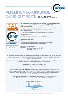
Award certificate OL 90 fanlight openers with hand lever and scissor stay gripping and cleaning scissor stay
VERLEIHUNGS-URKUNDE AWARD CERTIFICATE Nr./ No. 13-4/99 (Version 03) Der Güteausschuss der Gütegemeinschaft Schlösser und Beschläge e.V. verleiht aufgrund des vorliegenden Prüfberichtes gemäß RAL-GZ 607/12 dem Oberlichtbeschlag: Based upon the test report according to RAL-GZ 607/12 which has been released by the quality assurance commission of the quality assurance association of locks and hardware hereby awards the fanlight hardware: OL 90 Oberlichtöffner mit Handhebel sowie der Fangschere FPS OL 90 Fanlight opener with hand lever and the safety shear FPS Fensterwerkstoff: Holz Window material: Wood Die Prüfergebnisse sind auf andere Fensterwerkstoffe übertragbar. The test results are transferable for other window materials der Firma: the company: GEZE GmbH Reinhold-Vöster-Str. 21-29 D-71229 Leonberg im Rahmen der Mitgliedschaft bei der Gütegemeinschaft Schlösser und Beschläge e.V., das von RAL (Deutsches Institut für Gütesicherung und Kennzeichnung e.V.) anerkannte Gütezeichen Schlösser und Beschläge mit der Inschrift „Oberlichtbeschläge“ as part of the membership of the Gütegemeinschaft Schlösser und Beschläge e.V., the RAL-quality label shown below, having been recognized by the German RAL Institute for Quality Assurance and labelling „Fanlight hardware” geprüft nach RAL-GZ 607/12, Ausgabe … certified according to RAL-GZ 607/12, version … Die Führung des Zeichens Nr. 13-4/99 setzt die Einhaltung und Überwachung nach dieser Güte- und Prüfbestimmung voraus. Grundlage ist der Prüfbericht Nr. 13-4/99, 13-4/ … und 13-4/ … des PIV. Permission of using this RAL quality label no. 13-4/99 is based on the surveillance and the quality- and testing instructions. The basis is test report no. 13-4/99, 13-4/ … and 13-4/ … by PIV. Diese Urkunde hat insgesamt … Seite und ersetzt die Urkunde 13-4/99 vom … .2017. This certificate has a total of … page and replaces the certificate 13-4/99 from … .2017. D-42551 Velbert, 10. Juli/ July 2024 Geschäftsführer Managing Director FB_07_13_02_20 Gütegemeinschaft Schlösser und Beschläge e.V. ∙ Offerstraße 12 ∙ D-42551 Velbert
(PDF | 351 KB)
Declaration of conformity E 170 230 V and E 212
(PDF | 194 KB)

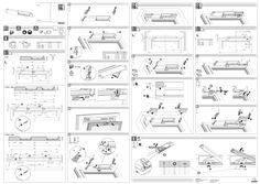
RWA 100 NT window system
… .2 RWA 100 NT Solo Bohrbilder (falls Bohrlehre nicht vorhanden) 27 Der Motor kann links oder rechts montiert werden. Ab 1,2 m2 Fensterfläche müssen … Verriegelungen montiert werden. Die zweite Verriegelung wird je nach Verhältnis von Höhe und Breite platziert. … .2 Verriegelung Zusatzwinkel bei Überschlaghöhe Ü bis 12 Fensteranlage … 7 290 mm … 520-1700 mm Anschlagmaß Auflaufbock (zusätzlich bei Kunststofffenstern zu verwenden) Flügelaußenkante Eckumlenkung (7) ggf. um 50 mm kürzen Montage der Zugstange LZ 520-1700 mm 11 12 23 24 mm Zusatzwinkel erforderlich Endkappe und Abdeckung (Montage siehe Kapitel … .7) 27 50 mm 1700 mm DE Montageanleitung 30° 520 mm 520-1700 mm RWA 100 NT Bohrbild für Eckumlenkung … 4 … 15 20° 13 b 520-1700 mm 520-1200 mm … 6 520-1400 mm LZ System einwärts, 24 V DC … .3 XX XX RWA 100 NT Syncro 154761-00 Symbole und Darstellungsmittel WARNUNG VORSICHT – VORSICHT Bedeutung Gefahren für Personen. Nichtbeachtung führt zu Tod oder schweren Verletzungen. Gefahren für Personen. Nichtbeachtung kann zu Tod oder schweren Verletzungen führen. Gefahren für Personen. Nichtbeachtung kann zu leichten Verletzungen führen. Entriegelungsfeder (6) montieren. Zugstange von unten durch die Entriegelungsfeder (6) einführen. Klemmstück (2) oberhalb der Entriegelungsfeder (6) aufsetzen. Zugstange in Eckumlenkung (7) einführen und festklemmen. Zugstange in Entriegelungsfeder (6) festklemmen. XX XX XX XX ≥ 800 mm 520-1600 mm … Anschlagmaße nach Antriebshub … .1 RWA 100 NT Informationen zur Vermeidung von Sachschäden, zum Verständnis oder zum Optimieren der Arbeitsabläufe. … .3 b G Montage der Querstange XX b Um die korrekte Bedienung zu verdeutlichen, sind wichtige Informationen und technische Hinweise besonders herausgestellt. Symbol 520 mm GEFAHR XX 20° 800-2400 mm Warnsymbol Warnwort … mm Bei Platzmangel (z. B. in Leibungen) die Zugstange vor Montage der Entriegelungsfeder einführen. Zugstange ggf. aussparen, damit die Befestigungsschrauben mit dem Schraubendreher erreicht werden können. a 800 mm In dieser Anleitung werden Warnhinweise verwendet, um Sie vor Sach- und Personenschäden zu warnen. XX Lesen und beachten Sie diese Warnhinweise immer. XX Befolgen Sie alle Maßnahmen, die mit dem Warnsymbol und Warnwort gekennzeichnet sind. Zugstange ablängen: àà LZ = Länge Zugstange [mm] = b – G – E + 335 Zugstange leicht einfetten. XX 520 mm 520 mm a 800 mm Länge Zugstange ~300 mm 530 mm * ≥620 mm mit … Verriegelungen XX Flügelhöhe XX Querstange ablängen: àà LQ = Länge Querstange [mm] = f1 – 77 Querstange leicht einfetten und einschieben. Querstange auf Eckumlenkung (7) und Verriegelung (4) festklemmen. E ~2 mm Bedeutung bedeutet „Wichtiger Hinweis“ Bohrbild für Verriegelungen 28 bedeutet „Zusätzliche Information“ RWA 100 NT Solo 28 16 Bohrbild Verriegelung mit Endkappe Verriegelungsteil unverriegelt (Abstand ca. … mm) mV mit Verschiebung von 50 mm oder bündig (siehe nachstehende Tabelle) XX … .4 Symbol für eine Handlung: Hier müssen Sie etwas tun. XX Halten Sie bei mehreren Handlungsschritten die Reihenfolge ein. Montage der Klappkonsole Gemäß der im Produkthaftungsgesetz definierten Haftung des Herstellers für seine Produkte sind die in dieser Broschüre enthaltenen Informationen (Produktinformationen und bestimmungsgemäße Verwendung, Fehlgebrauch, Produktleistung, Produktwartung, Informations- und Instruktionspflichten) zu beachten. Die Nichtbeachtung entbindet den Hersteller von seiner Haftungspflicht. Allgemeine Hinweise … Produktbeschreibung 30 Flügelhöhe b Maß G Maß E Öffnungs[mm] [mm] [mm] winkel Hub 100 * 520–600 65 365 ca. 34° 600–700 85 365 ca. 32° 700–800 125 365 ca. 28° 800–850 145 365 ca. 26° Hub 150 * 610–630 100 415 ca. 49° * 630–700 115 415 ca. 47° * 700–800 150 435 ca. 42° 800–900 200 460 ca. 36° 900–1000 275 460 ca. 31° Hub 200 * 700–720 145 465 ca. 58° * 720–800 160 465 ca. 55° * 800–900 215 485 ca. 47° * 900–1000 275 510 ca. 41° 1000–1100 325 510 ca. 37° 1100–1200 425 510 ca. 31° 1200–1300 525 510 ca. 27° Hub 300 * 950–1000 290 560 ca. 58° * 1000–1050 335 570 ca. 53° * 1050–1100 350 570 ca. 51° * 1100–1150 415 580 ca. 46° * 1150–1250 465 580 ca. 43° 1250–1320 495 610 ca. 41° 1320–1400 565 610 ca. 38° 1400–1500 645 610 ca. 34° 1500–1600 715 610 ca. 32° 1600–1700 815 610 ca. 29° * Eckumlenkung um 50 mm kürzen. Die Fensteranlage ist ein Antriebssystem zum Öffnen und Schließen von vertikal eingebauten Kipp-, Klapp- und Drehfenstern, die einwärts geöffnet werden. Je nach Anwendung werden … System (Solo) oder … Systeme (Syncro) neben dem Fenster montiert. Lieferbar für 24 V DC. … Bestimmungsgemäße Verwendung Der Antrieb ist ausschließlich für den Einsatz in trockenen Räumen bestimmt. Es dürfen nur die im Kabelplan angegebenen Kabel verwendet werden und für Litzen müssen grundsätzlich isolierte Adernhülsen verwendet werden. Anderer Einsatz als der bestimmungsgemäße Gebrauch sowie alle Veränderungen am Produkt sind unzulässig. … Haftungsbeschränkung Die Firma GEZE GmbH übernimmt keinerlei Haftung für direkte oder indirekte Schäden, welche sich aufgrund der Nichteinhaltung der Angaben in dieser Anleitung zu dieser Fensteranlage ergeben. Technische Änderungen, welche zur Verbesserung oder Weiterentwicklung des Produktes dienen, können jederzeit ohne besondere Ankündigung eingeführt werden. Eigenmächtige Änderungen an der Anlage schließen jede Haftung von GEZE für resultierende Schäden aus. Bei Kombination mit Fremdfabrikaten übernimmt GEZE keine Gewährleistung. Auch für Reparatur- und Wartungsarbeiten dürfen nur GEZE Originalteile verwendet werden. Weitere Informationen erhalten Sie gerne bei unserem Kundendienst … Sicherheitshinweise àà Vorgeschriebene Montage, Wartungs- und Instandsetzungsarbeiten müssen von Sachkundigen durchgeführt werden, die von GEZE autorisiert sind. àà Der Anschluss an Netzspannung (24 V DC) und alle Arbeiten an der Elektrik müssen von einer Elektrofachkraft entsprechenden dem jeweiligen Anschlussplan durchgeführt werden. àà Netzanschluss und Schutzleiterprüfung müssen nach VDE 0100 durchgeführt werden. àà Als netzseitige Trenneinrichtung muss ein bauseitiger Sicherungsautomat entsprechend der zulässigen Strombelastbarkeit des Kabels verwendet werden. àà Für sicherheitstechnische Prüfungen müssen die länderspezifischen Gesetze und Vorschriften beachtet werden. àà Gemäß der Maschinenrichtlinie 2006/42/EG muss vor Inbetriebnahme der Fensteranlage eine Sicherheitsanalyse (Gefahrenanalyse) durchgeführt werden und die Fensteranlage gemäß der CE-Kennzeichnungsrichtlinie 93/68/EWG gekennzeichnet werden. àà Den neuesten Stand von Richtlinien, Normen und länderspezifischen Vorschriften beachten, insbesondere: àà BGR 232 „Richtlinien für kraftbetätigte Fenster, Türen, Tore“ àà DIN 18650 „Schlösser und Beschläge - Automatische Türsysteme“ àà VDE 0100; Teil 610 „Errichten von Niederspannungsanlagen“ àà VDE 0700; Teil 238 „Sicherheit elektrischer Geräte für den Hausgebrauch und ähnliche Zwecke, Antriebe für Fenster, Türen, Tore und ähnliche Anlagen“ àà Unfallverhütungsvorschriften, insbesonderen BGV A1 „Grundsätze der Prävention“ und BGV A2 „Elektrische Anlagen und Betriebsmittel“ … Öffnungsweite Verschiebung [mm] [mm] ca. 350 ca. 380 ca. 380 ca. 400 45 45 45 45 ca. 520 ca. 520 ca. 560 ca. 550 ca. 520 45 45 25 ca. 690 ca. 720 ca. 710 ca. 690 ca. 690 ca. 650 ca. 610 45 45 25 ca. 970 ca. 930 ca. 950 ca. 900 ca. 900 ca. 920 ca. 890 ca. 870 ca. 860 ca. 830 50 40 40 30 30 XX XX … .5 Montage der Winkelübertragung … Montagevorbereitung XX XX Für eine bessere Stabilität bei allen Fensterarten auf der Antriebsseite ein Zusatzband montieren. Sicherstellen, dass bei Kunststofffenstern mit Stahlarmierung auf der Antriebsseite ein Auflaufbock (bauseits) eingesetzt wird. Die angegebenen Anschlagmaße in den folgenden Kapiteln gelten für die Montage auf der linken Seite. XX Anschlagmaße für die rechte Seite spiegelbildlich verwenden. … XX Bauteilanordnung und Maße XX … .6 XX XX 11 12 13 14 XX … 15 ≥ 495 mm mit … Verriegelungen Anschlagmaß Auflaufbock Bohrbild Eckumlenkung Bohrbild Verriegelung zwischen Beschlagteilen (2. Verriegelung) Anordnung und Teileübersicht am Fenster … RWA 100 NT Solo 16 17 18 19 20 3c Vorspannschraube (3c) in den E-Antrieb eindrehen: àà 22 mm Abstand lassen, wenn Spindel nicht ausgefahren wurde. – oder – àà Komplett anziehen, wenn Spindel um 22 mm ausgefahren wurde. f1 ≥ 495 mm mit … Verriegelungen 11 Anschlagmaß 15 bei Überschlaghöhen Ü bis 12 mm Zusatzwinkel erforderlich 23 Flügelaußenkante Bohrbild für Antriebsbefestigung 3c Konsolenunterteil und -oberteil so ausrichten, dass Senkschraube (36) (M5×40) durchgesteckt werden kann. 11 17 18 19 20 23 X Anschlagmaß Bohrbild Stangenführung Bohrbild Entriegelungsfeder Bohrbild Angriffswinkel … Bänder auf Antriebsseite Flügelaußenkante Platzbedarf für Antriebsteile 37 … mm 36 37 38 XX … 1 3b Vorspannschraube (3c) mit Winkelübertragung (3b) und E-Antrieb (30) verbinden. Bohrungen (mit Bohrlehre) … 8 Wenn möglich, Spindel mit Einstellgerät um 22 mm ausfahren. 38 XX … 3a 36 bei Ü bis 12 mm Zusatzwinkel erforderlich Bohrbild Verriegelung mit Endkappe Bohrbild Stangenführung Bohrbild Entriegelungsfeder Bohrbild Angriffswinkel … Bänder auf E-Antriebseite Die Befestigungsschrauben werden nicht mitgeliefert. Einziehmuttern bei Leichtmetall- und Kunststofffenstern empfohlen. … 3b Das Maß von 22 mm ist wichtig für den Verriegelungshub. Es lässt sich entweder vorab mit dem Einstellgerät über die Spindel einstellen oder über die Vorspannschraube einhalten. f1 Ø Bohrung … mm … mm 31 Winkelübertragung (3b) auf Angriffswinkel (3a) montieren. Einstellschraube (31) (M10×4; Länge 10 bis 13 mm) in Winkelübertragung (3b) einschrauben. Montage des E-Antriebs XX Grau hinterlegte Positions-Nummern verweisen auf Bohrbilder Fenstertyp Befestigungsschrauben Holz Senkholzschrauben 5×35 DIN 97 oder 7997 Leichtmetall Senkblechschrauben 4,8×22 DIN 7972 oder 7982 Senkschrauben M5×20 DIN 963 oder 965 Kunststoff Senkblechschrauben 4,8×L DIN 7972 oder 7982 Empfehlung: Schraube (Länge L) muss durch min. … Profilwandungen gehen Eckumlenkungsklemmstück in unverriegeltem Zustand hier bündig Sechskantmutter SW17 Schrauben M6×12 Schrauben M8×8 32 33 34 35 Werkzeuge und Befestigungsmittel Größe – – – – Ø … mm (3 mm) SW 3, SW … SW 17 – – – Konsolenoberteil (1b; für RWA 100 NT) auf Klemmstück (2) mit Schrauben M6x12 (34) montieren. Sonder G-Maße für größere Öffnungsweiten auf Anfrage oder über das GEZE Kundenportal im Internet Sicherheitshinweise zur Arbeit an elektrischen Anlagen und im Anschlussplan beachten. Werkzeug Maßband Anreißwerkzeug Bohrlehre Bohrwerkzeug Bohrer Innensechskant-Schlüssel … Gabelschlüssel Schraubendreher Säge Feile 29 14 Bohrbild Verriegelung zwischen Beschlagteilen (2. Verriegelung) àà Arbeitsplatz gegen unbefugtes Betreten sichern. àà Schwenkbereich langer Anlageteile beachten. àà Vor Arbeiten an der elektrischen Anlage die Spannungszufuhr unterbrechen und die Spannungsfreiheit sicherstellen. Bei Verwendung einer unterbrechungsfreien Stromversorgung (USV) bleibt die Anlage trotz netzseitiger Freischaltung unter Spannung. àà Verletzungsgefahr bei geöffnetem Antrieb durch scharfe Kanten und bewegliche Teile (Einziehen von Haaren, Kleidungsstücken, …). àà Verletzungsgefahr durch nicht gesicherte Quetsch-, Stoß-, Scher- und Einzugstellen. àà Verletzungsgefahr durch Glasbruch. àà Antrieb beim Einrichten nur im Tastbetrieb steuern. Anfassen der Fensteranlage während des Betriebs kann zu Verletzungen führen. àà Zur Vermeidung von Verletzungen die beiliegenden Schutzkappen auf überstehende Gewinde der Befestigungsschrauben drehen. … 1a … Sicherheitsbewusstes Arbeiten XX Konsolenunterteil (1a) mit … Schrauben (29) (M5×10) am E-Antrieb (30) festschrauben (bündig oder um 50 mm verschoben). 22 mm … 1a 1a 29 mV = 50 mm Produkthaftung Senkschraube M5x40 Spindelantrieb E 250 NT Spindelantrieb E 350 N 36 Konsolenunterteil auf Stange festklemmen. Konsolenteile mit Senkschraube (36) verbinden. XX Vorspannschraube anziehen oder Spindel einfahren (22 mm) und Fenster verriegeln. XX Position der Verriegelungsteile (39) kontrollieren und ggf. nachstellen. 10 … 6 … Platzbedarf für Antriebsteile (Ansicht: X) 39 39 Klappkonsole Klemmstück Angriffswinkel Verriegelung Zusatzwinkel … 7 … 9 10 Entriegelungsfeder Eckumlenkung Stangenführung – Spindelantrieb E 250 NT für Angriffswinkel für Verriegelung für Zusatzwinkel für Entriegelungsfeder für Eckumlenkung Stangenführung bündig mit Flügelkante Bohrbild für entsprechende Beschlagteile auswählen … .7 Riegelteil in Riegelwinkel eingefahren Montage der Abdeckungen XX L1 Abdeckprofile ablängen: àà … Verriegelung: L1 = f1 – 83 mm L2 = b – G – E + 22 mm L2 … 2 … 4 … 3 … 5 … 7 … 21 Mit … Verriegelungen: RWA 100 NT Syncro f2 … Montagereihenfolge … .1 Befestigung der Komponenten f2 a a L1 àà … Verriegelung je Seite mit durchgehendem Abdeckprofil: L1 = f2 – 85 mm L2 = b – G – E + 22 mm L3 = a – … × f2 – 146 mm 26 f1 L3 L1 37 … 50 mm f1 8b L1.1 L2 … L1 àà … Verriegelungen: L1 = f2 – 85 mm L1.1 = f1 – f2 – 194 mm L2 = b – G – E + 22 mm siehe Bohrbilder rechts L2 Bohrungen (ohne Bohrlehre) L2 … .1 … XX 8a Ggf. Endkappen montieren. Verriegelungsabdeckungen und Abdeckprofile einklipsen. … 6 … 5 Inbetriebnahme und elektrische Montage siehe Anschlussplan (ID 148327) 25 … RWA 100 NT f1 = min. 285 mm f2 = min. 265 mm (Anschlagmaß bei Montage mit durchgehendem Abdeckprofil) … Montagemöglichkeiten … .1 Einbaubedingungen XX a a b XX b b a Kippfenster XX Klappfenster Drehfenster XX XX b Flügelbreite Flügelhöhe Überschlag Abstand zwischen Flügeloberkante und Stangenmitte Anschlagmaße festlegen: àà Maß G und E (siehe Kapitel … .1) àà Maß f1 bzw. f2 (siehe Kapitel … ) Befestigungslöcher bohren (siehe Kapitel … ). Eckumlenkung (7), Stangenführung (8), Angriffswinkel (3) und Verriegelungen (4) ohne Endkappe montieren. àà Eckumlenkung (7) ggf. um 50 mm kürzen (siehe Kapitel … ). Bei Bedarf Schutzkappen auf Enden der Befestigungsschrauben drehen. Bei Überschlaghöhen bis 12 mm (15) den Zusatzwinkel (5) montieren. L-Metall fächenbündig 15 Einbaubedingungen Kunststoff XX … Periodische Überwachung, Wartung XX XX … Maßnahmen zur Absicherung bzw. Vermeidung von Quetsch-, Stoß-, Scher- und Einzugstellen prüfen. Feststellschrauben von E-Antrieb und Rahmenwinkel unbedingt fest anziehen. Das System mindestens einmal jährlich warten. Funktion prüfen. Zustand von Mechanik und Stromleitung prüfen. Entsorgung Die Fensteranlage besteht aus Materialien, die der Wiederverwertung zugeführt werden sollten. XX Die Einzelkomponenten entsprechend ihrer Materialart sortieren: àà Aluminium (Profile) àà Eisen (Schrauben usw.) àà Kunststoffe àà Elektronikteile (Motor, Steuerung, Transformator, Relais usw.) àà Kabel Die Teile können beim örtlichen Wertstoffhof oder durch ein Schrottverwertungsunternehmen entsorgt werden. L-Metall Überschlag 15 Holz B2 àà Die Fensterlager und deren Befestigungen müssen einer statischen Belastung von 1000 N standhalten. àà Bei Kunststofffenstern muss zusätzlich ein Auflaufbock angebracht werden. … mm B1 XX XX Schnittdarstellungen der Verriegelung a àà Auf der Motorseite müssen … Bänder (B1 und B2) montiert werden. 25 26 Platzmangel entfallen) Stangenführung (erforderlich bei Stangenlänge ≥600 mm) Antriebsseite Verriegelungsseite 14–18 mm Ü a b Ü D 8b 19 mm D Angriffswinkel Verriegelung Zusatzwinkel Eckumlenkung Stangenführung (kann bei 19 mm Montage … 4 … 7 8a Abschließende Prüfung 14-18 mm … 7 Ü > 12 mm Ü > 12 mm Platzbedarf für Antriebsteile (Ansicht: X) … .2 Mounting of the connecting rod The motor can be mounted on the left or right. Above … m window surface … locking units have to be mounted. The second locking unit is placed depending on the height and width. … 7 LZ 520-1200 mm 520-1700 mm Drilling templates (if no drill jig available) 13 Drilling template for corner transmission 11 12 23 24 Mounting dimension Limiter (must be used for PVC Windows) Outer edge of casement Shorten the corner transmission (7) by 50 mm, if appropriate b RWA 100 NT Solo 50 mm … .2 … 6 LZ XX XX Shorten the connecting rod: àà LZ = Connecting rod length [mm] = b – G – E + 335 Lightly lubricate the connecting rod. … mm XX If the space is insufficient (e.g. in soffits), introduce the connecting rod before mounting the unlocking spring. If necessary, cut a recess in the connecting rod so that the fastening screws can be reached with the screw driver. XX Mount the unlocking spring (6). Insert the connecting rod from below through the unlocking spring (6). Place the clamping piece (2) above the unlocking spring (6). Insert the connecting rod into the corner transmission (7) and clamp it tight. Clamp the connecting rod into unlocking spring (6). 290 mm 520-1700 mm 520-1700 mm Window unit Connecting rod length ~300 mm 1700 mm GB Mounting instructions 30° 520 mm 520-1700 mm RWA 100NT 20° 520-1400 mm 530 mm XX * ≥620 mm with … locking units XX Inward-opening system 24 V DC XX … .3 XX RWA 100 NT Syncro a 800 mm 154761-00 Symbols and means of representation CAUTION Danger for persons. Non-compliance can result in minor injuries. CAUTION Information on avoiding material damage, understanding a concept or optimising the processes. 520-1600 mm … .4 ≥ 800 mm … Mounting dimensions depending on drive stroke … .1 RWA 100 NT G Mounting of the top-hung bracket 30 E XX RWA 100 NT Solo Symbol for an action: Here you have to do something. XX Observe the sequence if there are several action steps. Product liability Product description Casement height b [mm] Stroke 100 * 520–600 600–700 700–800 800–850 Intended use The drive is designed solely for use in dry rooms. Use only cables specified in the cable plan. Insulated wire end ferrules must always be used for wire-end ferrules. Any other use than the proper use as well as all changes to the product are impermissible. Limitation of liability GEZE GmbH does not accept any liability for direct or indirect damage resulting from the non-observance of the specifications in these instructions of this window unit. Technical modifications that serve the improvement or further development of the product can be introduced at any time without any particular announcement. GEZE shall not be liable for injuries or damage resulting from unauthorised modification of the system. GEZE shall not be liable if products from other manufacturers are used with GEZE equipment. Only original GEZE parts may be used for repair and maintenance work as well. For further information please contact our customer service. Opening With displ. width [mm] [mm] 65 85 125 145 aprox. 34° aprox. 350 aprox. 32° aprox. 380 aprox. 28° aprox. 380 aprox. 26° aprox. 400 365 365 365 365 … .5 … Mounting the angle transmission aprox. 520 45 45 25 aprox. 520 aprox. 560 aprox. 550 aprox. 520 aprox. 690 45 45 25 aprox. 720 aprox. 710 aprox. 690 aprox. 690 aprox. 650 aprox. 610 aprox. 970 50 40 40 30 30 aprox. 930 aprox. 950 aprox. 900 aprox. 900 aprox. 890 aprox. 870 aprox. 860 aprox. 830 XX XX XX Mount an additional hinge on the drive side to improve stability at all the window types. Ensure that a limiter (not included) is used at the drive side for plastic windows with steel reinforcement. … .6 XX The mounting dimensions specified in the following chapters apply for mounting on the left-hand side. XX Use the mounting dimensions for the right-hand side laterally reversed. … Component layout and dimensions XX XX XX Location and overview of parts at the window … RWA 100 NT Solo If possible, use the synchronising unit to extend the spindle by 22 mm. 16 f1 ≥ 495 mm with … locking units 11 Mounting dimension 12 Limiter 13 Drilling template for corner transmission 14 Drilling template for locking unit between fittings (2nd locking unit) 15 Additional bracket required for O up to 12 mm … Drilling template for locking unit with end cap Drilling template for rod guide Drilling template for unlocking spring Drilling template for toe bracket … hinges on electrically operated drive side 17 18 19 20 36 37 38 XX XX Holes (with drilling pattern) Ø hole Align the lower and upper bracket parts so that the countersunk screw (36) (M5×40) can be passed through. Countersunk screw M5x40 Spindle drive E 250 NT Spindle drive E 350 N 36 Clamp the lower bracket section onto the rod. Connect the bracket sections with the countersunk screw (36). XX Check the position of the locking parts (39) and, if necessary, adjust. 39 … .7 Locking element retracted into locking position. Mounting the covers 10 … L1 Shorten the cover profile: àà … locking unit: L1 = f1 – 83 mm L2 = b – G – E + 22 mm L1 … 4 … 6 … 8 21 … Unlocking spring Corner transmission Rod guide – Spindle drive E 250 NT … .1 for Toe bracket for Locking unit for Additional bracket for Unlocking spring for Corner transmission Rod guide flush with casement edge Select the drilling template for the corresponding fittings àà … locking unit per side with continuous cover profile: L1 = f2 – 85 mm L2 = b – G – E + 22 mm L3 = a – … × f2 – 146 mm … L1 Space required for drive parts (View: X) L3 L1 37 Holes (without drilling pattern) see Drilling templates on the right With … locking units: L1.1 L2 àà … locking units: L1 = f2 – 85 mm L1.1 = f1 – f2 – 194 mm L2 = b – G – E + 22 mm … 7 … 9 10 … Mounting sequence … .1 Fastening of the components … XX If necessary, mount the end caps. Clip in the locking unit covers and cover profiles. … 8b Commissioning and electrical installation see wiring diagram ID 148327 26 RWA 100 NT Syncro … f2 f1 f1 XX 8a … 3 a a XX … XX … 25 … RWA 100 NT f1 = min. 285 mm f2 = min. 265 mm (mounting dimension at mounting with continuous cover profile) … .1 Installation conditions XX XX XX a XX b Top-hung window D b L-metal overlap Side-hung window Casement width Casement height Overlap Distance between casement top edge and rod centre 15 Plastic 15 Wooden a … mm Ü a b O D L-metal flush 19 mm a b Bottom-hung window Define the mounting dimensions: àà Dimension G and E (see Section … .1) àà Dimension f1 or f2 (see Section … ) Drill the fitting holes (see Sections … ). E��������������������������������������������������������������������������� Mount the corner transmission (7), rod guide (8), toe bracket (3) and locking units (4) without end cap. Shorten the corner transmission (7) by 50 mm, if appropriate (see Sec. … ). If necessary, screw the protective caps onto the ends of the fastening screws. Mount the additional bracket (5) at overlap heights up to 12 mm (15). The window unit consists of materials that have to be recycled. XX Sort the individual components in accordance with the type of material: àà Aluminium (profiles) àà Iron (screws, etc.) àà Plastics àà Electronic components (motor, control, transformer, relay, etc.) àà Cables The parts can be disposed of at the local recycling station or a scrap processing company. Sectional views of the locking unit b a 25 26 Disposal 19 mm Mounting possibilities 8b Maintain the system at least once a year. Check the function. Check the state of the mechanical equipment and power cable. 14-18 mm … XX case of insufficient space) Rod guide (required for rod length ≥600 mm) Drive side Locking side 14–18 mm Mounting XX Toe bracket Locking unit Additional bracket Corner transmission Rod guide (can be left out in Check measures for securing parts and avoiding injuries due to trapping, knocking, shearing and hair, etc. being drawn in. It is imperative that the fixing screws of the electrically operated drive and the frame bracket be tightened. Periodic monitoring, maintenance XX … 3 … 5 … 8a Final check XX … 50 mm f2 … Further installation conditions àà … hinges (B1 and B2) have to be installed on the motor side. B1 Mounting dimension Drilling template for rod guide Drilling template for unlocking spring Drilling template for toe bracket … hinges on the drive side Outer edge of casement Space required for drive parts … mm XX Top-hung bracket Clamping piece Toe bracket Locking unit Additional bracket 11 17 18 19 20 23 X Tighten the pretensioning screw or retract the spindle (22 mm) and lock the window. … 1 … 3 … 5 f1 ≥ 495 mm with … locking units 11 Mounting dimension 15 Additional bracket required for overlap heights O up to 12 mm 23 Outer edge of casement Drilling template for drive fastening 37 XX … mm … mm … 1 3c Item numbers with a grey background refer to drilling templates 39 … 3c Turn the pretensioning screw (3c) into the electrically operated drive: àà Leave 22 mm space if the spindle has not been extended. – or – àà Tighten completely, if the spindle has been extended by 22 mm. … 7 3b Connect the pretensioning screw (3c) with the angle transmission (3b) and electrically operated drive (30). 38 Fastening screws are not included in the scope of delivery. Rivet nuts are recommended for light alloy and plastic windows. … 3a 36 Tools and fastening means Window Fastening screws type Wooden Countersunk wood screw 5×35 DIN 97 or 7997 Light alloy Countersunk head tapping screw … ×22 DIN 7972 or 7982 Countersunk screw M5×20 DIN 963 or 965 Plastic Countersunk head tapping screw 4.8xL DIN 7972 or 7982 Recommendation: Screw (length L) must pass through min. … mm profile cladding 3b The dimension of 22 mm is important in order to set the correct locking stroke. It can either be set in advance using the synchronising unit or held in place using the pretensioning screw. Observe the safety instructions for electrical systems and in the wiring diagram. Size – – – – Diameter … mm (3 mm) Size 3, Size … Size 17 – – – 14 Drilling template for locking unit between fittings (second locking unit) 31 Mount the angle transmission (3b) on the toe bracket (3a). Screw the adjustment screw (31) (M10×4; length 10 to 13 mm) into the angle transmission. Mounting the electrically operated drive Safety-conscious working Tool Tape measure Marking tools Drilling pattern Drilling tool Drill bits Allen key … open-ended spanners Screw driver Saw File Corner transmission clamping piece flush here in unlocked state Hexagon nut SW17 Screws M6×12 Screws M8×8 32 33 34 35 aprox. 920 Preparation of installation XX àà Secure the workplace against unauthorised entry. àà Take care to allow sufficient space for the movement of long components in the system. àà Before working on the electrical system interrupt the power supply and verify the safe isolation from supply. Note that the system will still be supplied with power, despite the fact that the power supply is disconnected, if an uninterruptible power supply (UPS) is used. àà Risk of injury by sharp edges and moving parts (drawing in of hair, clothing, …) when a drive is opened. àà Risk of injury by trapping, knocking, shearing and hair etc. being pulled in at unsecured points. àà Risk of injury through breakage of glass. àà During the setup control the drive only in inching mode. Touching the window unit can result in injuries during operation. àà In order to avoid injuries the enclosed protective caps are to be screwed onto projecting threads of the fastening screws. … Mount the upper bracket section (1b; for RWA 100 NT) on the clamping piece (2) using M6x12 (34) screws. 45 45 45 45 Special G dimensions for larger opening widths available on request or online via the GEZE Customer Portal. Safety instructions àà The prescribed mounting, maintenance and repair work must be performed by properly trained personnel authorised by GEZE. àà Connection to the mains voltage (24 V DC) and any work on electrical items must be carried out by a qualified electrician in accordance with the respective wiring diagram. àà The mains connection and safety earth conductor test must be carried out in accordance VDE 0100. àà Use a customer-accessible overload cut-out as the line-side disconnecting device in accordance with the permissible current carrying capacity of the cable. àà The country-specific laws and regulations are to be observed during safety-related tests. àà In accordance with Machine Directive 2006/42/EC, a danger analysis must be performed and the window system identified in accordance with CE Identification Directive 93/68/EEC before commissioning the window system. àà Observe the latest versions of guidelines, standards and country-specific regulations, in particular: àà BGR 232 “Guidelines for power-operated windows, doors and gates” àà DIN 18650 “Building hardware - Powered pedestrian doors” àà VDE 0100; Part 610 “Erection of low-voltage installations” àà VDE 0700, Part 238 “Safety of electrical devices for home use and similar purposes, drives for windows, doors, gates and similar systems” àà Accident-prevention regulations, especially BGV A1 “General regulations” and BGV A2 “Electrical systems and equipment” … Dimension Dimension Opening G [mm] E [mm] angle Stroke 150 * 610–630 100 415 aprox. 49° * 630–700 115 415 aprox. 47° * 700–800 150 435 aprox. 42° 800–900 200 460 aprox. 36° 900–1000 275 460 aprox. 31° Stroke 200 * 700–720 145 465 aprox. 58° * 720–800 160 465 aprox. 55° * 800–900 215 485 aprox. 47° * 900–1000 275 510 aprox. 41° 1000–1100 325 510 aprox. 37° 1100–1200 425 510 aprox. 31° 1200–1300 525 510 aprox. 27° Stroke 300 * 950–1000 290 560 aprox. 58° * 1000–1050 335 570 aprox. 53° * 1050–1100 350 570 aprox. 51° * 1100–1150 415 580 aprox. 46° * 1150–1250 465 580 aprox. 43° 1250–1320 495 610 aprox. 41° 1320–1400 565 610 aprox. 38° 1400–1500 645 610 aprox. 34° 1500–1600 715 610 aprox. 32° 1600–1700 815 610 aprox. 29° * Shorten the corner transmission by 50 mm.. The window unit is a drive system for opening and closing vertically installed bottom-hung, top-hung and side-hung windows that are opened inwards. Depending on the application, … system (Solo) or … systems (Syncro) are mounted next to the window. Available for 24 V DC. XX 16 Drilling template for locking unit with end cap L2 … Drilling template for locking units 29 22 mm General information … 1a L2 … Screw the lower bracket section (1a) with … screws (29) (M5×10) to the electrically operated drive (flush or displaced by 50 mm). … In accordance with the liability of the manufacturer for his products as defined in the German “Produkthaftungsgesetz” (Product Liability Act), the information contained in this brochure (product information and proper use, misuse, product performance, product maintenance, obligations to provide information and instructions) is to be observed. Non-compliance releases the manufacturer from his statutory liability. … 29 mV with displacement of 50 mm or flush (see following table) XX XX 1a 1a Meaning Means "important note" Means "additional information" Locking component unlocked (distance approx. … mm) b Casement height b Important information and technical notes are emphasised in order to illustrate the correct operation. Symbol 28 mV = 50 mm Danger for persons. Non-compliance can result in death or serious injuries. 28 520 mm WARNING 20° L2 – Danger for persons. Non-compliance will result in death or serious injuries. Shorten the cross rod: àà LQ = Cross rod length [mm] = f1 – 77 Lightly grease the cross rod and slide it in. Clamp the cross rod tight on the corner transmission (7) and locking unit (4). ~2 mm Warning word Meaning DANGER XX 800-2400 mm Warning symbol XX a 800 mm In these instructions, warnings are used to warn against material damage and injuries. XX Always read and observe these warnings. XX Observe all the measures that are marked with the warning symbol and warning word. Mounting the cross rod XX 520 mm 520 mm … .3 Ü > 12 mm B2 Ü > 12 mm 27 àà The window bearings and their fixings have to withstand a static load of 1000 N. àà A limiter has to be applied installed additionally at plastic windows. … Space required for drive parts (View: X) … 4 … 15 27 Locking unit Additional bracket Additional bracket required for overlap height O up to 12 mm End cap and cover (for mounting see Section … .7)
(PDF | 3 MB)